
Figure: (a) Effect of mesh non - uniformity on Laplacian: a mesh with uniform mesh spacing but non - constant number of neighbors of each triangle vertex. (b) Laplacian of

Figure:
(a) Effect of mesh non - uniformity on Laplacian:
a mesh with uniform mesh spacing but non - constant number
of neighbors of each triangle vertex.
(b) Laplacian of ![]() on mesh (a), using standard
stiffness matrix;
(c) Laplacian of
on mesh (a), using standard
stiffness matrix;
(c) Laplacian of ![]() on mesh (a), using modified
stiffness matrix,
eq.37.
on mesh (a), using modified
stiffness matrix,
eq.37.
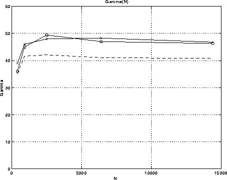
Figure 2:
Growth rate ![]() as a function of
number of mesh points N. The upper curves were obtained for zero
viscosity, by advancing the magnetic potential or the current.
The current advancement method gives somewhat larger
as a function of
number of mesh points N. The upper curves were obtained for zero
viscosity, by advancing the magnetic potential or the current.
The current advancement method gives somewhat larger ![]() for
low N, but the two methods agree closely for larger N.
The lower curve was obtained with viscosity
for
low N, but the two methods agree closely for larger N.
The lower curve was obtained with viscosity ![]() which
agrees with a previously reported, finite difference calculation.
which
agrees with a previously reported, finite difference calculation.
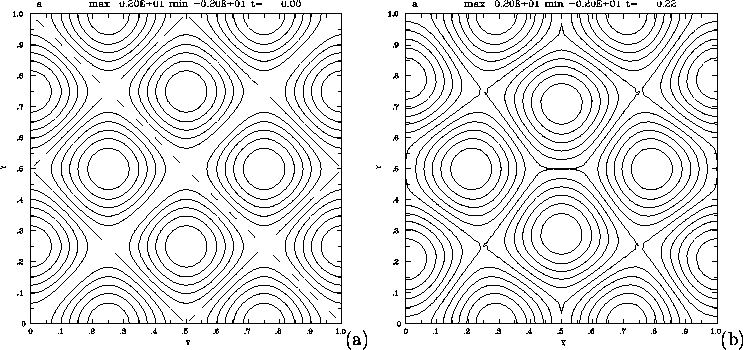
Figure 3:
(a) A calculation of the coalescence instability.
Contours of magnetic flux ![]() at time t = 0.
The flux forms a checkerboard diamond shaped pattern.
(b) Contours of magnetic flux
at time t = 0.
The flux forms a checkerboard diamond shaped pattern.
(b) Contours of magnetic flux ![]() at time t = 0.21
The diamonds have distorted to form pentagons.
Current sheets have formed along the short sides of the
pentagons.
at time t = 0.21
The diamonds have distorted to form pentagons.
Current sheets have formed along the short sides of the
pentagons.
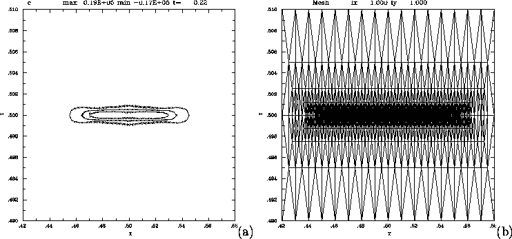
Figure 4:
(a) A blowup view of contours of current C at time t = 0.21
The view is centered on the separatrix, on short side of a flux
pentagon. The horizontal scale is about half of the scale ![]() of the previous figure, while the vertical scale is about
of the previous figure, while the vertical scale is about
![]() The current sheet has unremarkable structure.
(b) A blowup view of the mesh supporting the previous figure.
The mesh is highly refined along the current sheet, which is
well resolved. The minimum scale length of the mesh is
0.022 the size of the initial mesh separations.
The current sheet has unremarkable structure.
(b) A blowup view of the mesh supporting the previous figure.
The mesh is highly refined along the current sheet, which is
well resolved. The minimum scale length of the mesh is
0.022 the size of the initial mesh separations.
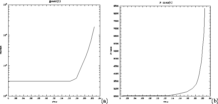
Figure 5:
(a) Time history of the log of the peak current density.
In the latter part of the run, the current density grows
exponentially, as indicated by the approximately
linear growth of the log of the peak current.
(b) Time history of the number of mesh points N.
In the latter part of the run, the number of mesh points grows
exponentially, keeping pace with the peak current density.
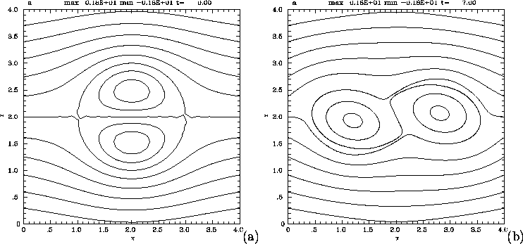
Figure 6:
(a) A calculation of the bipolar vortex tilt instability.
Contours of magnetic flux ![]() at time t = 0.
The flux contours consist of two interior flux systems, centered
on o - points, and an exterior flux system whose contours intersect
the boundary.
(b) Contours of magnetic flux
at time t = 0.
The flux contours consist of two interior flux systems, centered
on o - points, and an exterior flux system whose contours intersect
the boundary.
(b) Contours of magnetic flux ![]() at time t = 7.
The inner flux blobs have tilted from their
initial positions. The separatrix winds around the edges of
the tilted flux blobs.
at time t = 7.
The inner flux blobs have tilted from their
initial positions. The separatrix winds around the edges of
the tilted flux blobs.
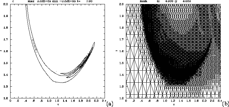
Figure 7:
(a) A blowup view of contours of current C at time t = 7.
The current is localized along the separatrix.
(b) A blowup view of the mesh, corresponding to the contours
in (a). The refinement is able to resolve the moving,
curved current sheet.
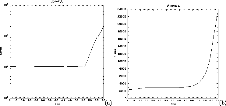
Figure 8:
(a) Time history of the log of the peak current density.
In the latter part of the run, the current density grows
exponentially, as indicated by the approximately
linear growth of the log of the peak current.
(b) Time history of the number of mesh points N.
In the latter part of the run, the number of mesh points grows
exponentially, keeping pace with the peak current density.
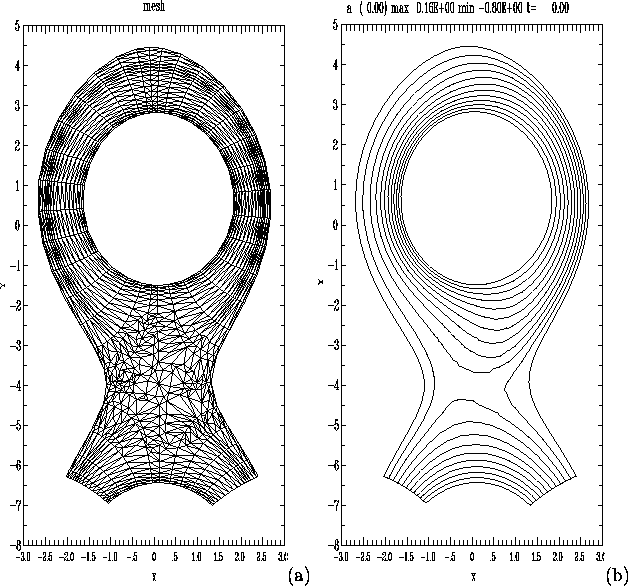
Figure 9:
(a) Mesh used for magnetic separatrix computation.
There are about 800 mesh points.
(b) Equilibrium magnetic flux function ![]() calculated
with 2D CRMHD, on a mesh like that of (a), but with about
four times as many mesh points.
calculated
with 2D CRMHD, on a mesh like that of (a), but with about
four times as many mesh points.